Navigation
Install the app
How to install the app on iOS
Follow along with the video below to see how to install our site as a web app on your home screen.
Note: This feature may not be available in some browsers.
More options
You are using an out of date browser. It may not display this or other websites correctly.
You should upgrade or use an alternative browser.
You should upgrade or use an alternative browser.
Adding SIMRAD GO7 to replace 3 gauge layout on 21 SL
- Thread starter Cw78
- Start date
Vikingstaff
Moderator
Here’s my 2017 SSBXP dash with Mercury digital garages and Simrad mounted up front and center.


bennyboat2
Member
- Messages
- 7
- Reaction score
- 9
It's been a minute but I finished the work. I added, changed, moved, installed the following
Once my orders were in I pulled the skirts off the side, but put 1/2 the bolts back because I realized these hold the logs on and didn't want to tweak anything towing it around the property to work on it.

All the wiring and plumbing that I had to run moved a few inches at a time, pulling, then pushing so that I didn't chaff anything. I ended up pulling a small 8x12" panel on the starboard rear between the center and right log, this gave me enough access to run the wiring over the rats nest that is Bennington factory wiring. I swear, nothing is streamline, everything is in a loom and knotted over fuel lines or other looms from the factory. I guess that's assembly line factory boating...


I lucked out and my first snake for the fuel lines went to the right spot center stern to starboard. Pulling them back was a different story because they are rubber and the spaces are tight, I only cut my hands up a dozen times or so.
Removing the old striker4 ducer proved tougher than I first thought. Bennington used 5 wire loom clamps to hold it across the beam L > R. I ended up taping a razor knife w/ a carpet hook on the end of a piece of strapping so I could cut the loops past arms reach and pull the old ducer cable out. I reused what the looms I could reach to hold the new side scan ducer that came w/ the Go7 and the wires in middle just drape on the sea skirt.
Once I had everything in hand I did some bench wiring, I only needed 2 wires from the whole fuel paddle harness (plus a ground) so I cut out what I didn't need an sealed it all up. The ground runs from the tank sender, back into the engine compartment, back out to the fuel water separator then it taps off and goes to the battery. The amount of wire Mercury gives you w/ the paddle kits is crazy.


Here's the finished pictures.
VVL terminated Cable

Fuel Paddle Engine Harness

Fuel Water Separator

Old Battery

Second Battery, Switch and relocation

NMEA Bus, VVL and added 12V bus under console

Old Console Backside

Empty Console

New Console Blank

Old Console and FF


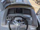
New Console

There is still a bit of work to do. I'd like to run phone chargers to all the seats and take some time to clean the boat up. I have been rushing to get onto the water but we finally made it out.
Thanks again Potomacbassin for the help and everyone for sharing this pictures and input. Don, if you read this thanks for advice and the time you spent going over the wiring. I made sure to not allow the factory 5v harness ground have a chance to ground to the boat and cause the PCM issues you warned of.
- Go7
- Mercury Vessel View Link
- Terminated 25' data cable
- Fuel Paddle harness, for tank level
- NMEA bus
- 12v bus
- New console trim
- Fuel water separator
- Second battery and switch
- New fuel lines
- Scanstrutt Rokk Edge Inductive charger
- Various USB, power delivery ports
Once my orders were in I pulled the skirts off the side, but put 1/2 the bolts back because I realized these hold the logs on and didn't want to tweak anything towing it around the property to work on it.
All the wiring and plumbing that I had to run moved a few inches at a time, pulling, then pushing so that I didn't chaff anything. I ended up pulling a small 8x12" panel on the starboard rear between the center and right log, this gave me enough access to run the wiring over the rats nest that is Bennington factory wiring. I swear, nothing is streamline, everything is in a loom and knotted over fuel lines or other looms from the factory. I guess that's assembly line factory boating...
I lucked out and my first snake for the fuel lines went to the right spot center stern to starboard. Pulling them back was a different story because they are rubber and the spaces are tight, I only cut my hands up a dozen times or so.
Removing the old striker4 ducer proved tougher than I first thought. Bennington used 5 wire loom clamps to hold it across the beam L > R. I ended up taping a razor knife w/ a carpet hook on the end of a piece of strapping so I could cut the loops past arms reach and pull the old ducer cable out. I reused what the looms I could reach to hold the new side scan ducer that came w/ the Go7 and the wires in middle just drape on the sea skirt.
Once I had everything in hand I did some bench wiring, I only needed 2 wires from the whole fuel paddle harness (plus a ground) so I cut out what I didn't need an sealed it all up. The ground runs from the tank sender, back into the engine compartment, back out to the fuel water separator then it taps off and goes to the battery. The amount of wire Mercury gives you w/ the paddle kits is crazy.
Here's the finished pictures.
VVL terminated Cable
Fuel Paddle Engine Harness
Fuel Water Separator
Old Battery
Second Battery, Switch and relocation
NMEA Bus, VVL and added 12V bus under console
Old Console Backside
Empty Console
New Console Blank
Old Console and FF
New Console
There is still a bit of work to do. I'd like to run phone chargers to all the seats and take some time to clean the boat up. I have been rushing to get onto the water but we finally made it out.
Thanks again Potomacbassin for the help and everyone for sharing this pictures and input. Don, if you read this thanks for advice and the time you spent going over the wiring. I made sure to not allow the factory 5v harness ground have a chance to ground to the boat and cause the PCM issues you warned of.
Vikingstaff
Moderator
Fantastic follow. Looks so professionally well done in the “after” picks. Great work. You certainly earned some water time!!!
sunedog
Well-Known Member
- Messages
- 666
- Reaction score
- 1,241
Great job on the installs and thanks so much for documenting your project so thoroughly for us.
Very nice job with the installation and documentation. Your dash looks exactly like my 2020 Bennington with a GO7. Your wiring looks better organized than mine.
In your under the console photo with the VVL, NMEA Bus, and 12V bus, it looks like your memory card slot on the VVL facing your 12V bus. The reason I ask is that the memory slot is used for updates to the VVL software which seems to happen every year or two. If it is facing the 12V bus and is hard to get to, you may want to rotate the VVL.
The memory slot on my VVL is facing down and is located near the floor. It can be a pain to insert and remove the memory card when there are updates.
Thanks for sharing your installation.
bennyboat2
Member
- Messages
- 7
- Reaction score
- 9
Thanks for the tip. Two of the screws on the VVL were in a very very tight spot. I was able to sink the third screw 50% before it stripped. I just left it, it's not like I'm going to the moon on this thing... If I can't get the micro in using a pair of pliers I'll think about cutting the screw and rotating it, but it's in place for now....If it is facing the 12V bus and is hard to get to, you may want to rotate the VVL.
The only issue I'm having with this setup is the sun cover doesn't fit on the simrad. It sits so tight in the hole that there isn't enough room for it to sit on the face and clip on the side. I may need to shave the detents on the cover that hold it inplace and just let gravity keep it on, or take the outside edges of the cover to belt sander and thin the plastic out. Does anyone else have that problem? Is there a spacer you can put in the hole to hold it out a CM and give the relief needed to keep the cover on? I'm curious what the factory sandwich is like. Mine is console, gasket, simrad, simrad trim.
Thanks
I had a similar problem with the sun cover. For me it was impossible to remove or install it, but somehow my wife could do it by slightly bending the cover. Plus, her fingers are much smaller than mine which helped her remove it.
Edit: However, your gap on the sides looks much tighter than mine.

Edit: However, your gap on the sides looks much tighter than mine.
I tried several different covers that would not fit because it is too tight. I tried some static cling that is used for signs, but it didn't work very well.Thanks for the tip. Two of the screws on the VVL were in a very very tight spot. I was able to sink the third screw 50% before it stripped. I just left it, it's not like I'm going to the moon on this thing... If I can't get the micro in using a pair of pliers I'll think about cutting the screw and rotating it, but it's in place for now.
The only issue I'm having with this setup is the sun cover doesn't fit on the simrad. It sits so tight in the hole that there isn't enough room for it to sit on the face and clip on the side. I may need to shave the detents on the cover that hold it inplace and just let gravity keep it on, or take the outside edges of the cover to belt sander and thin the plastic out. Does anyone else have that problem? Is there a spacer you can put in the hole to hold it out a CM and give the relief needed to keep the cover on? I'm curious what the factory sandwich is like. Mine is console, gasket, simrad, simrad trim.
Thanks
I'm also interested if some has come up with a cover. Right now I use a towel to cover it.
Potomacbassin’
Well-Known Member
For those with a tight cover, can you just use a narrow strip of fabric that sits under the cover and has its two ends exposed? So to remove the cover, just pull both ends of the fabric that then lifts the cover? Probably many macgyver-esque solutions out there...
bennyboat2
Member
- Messages
- 7
- Reaction score
- 9
That's not a bad idea and I'll use it until I can 3d print a few versions that are thinner. If they work, I'm going to sand down the original, I just don't want to mess it up until I know it will work. I'll put some picture up as I move along this project.
For now, here are the midcleats... anchor non lifting points installed.


Yes they are not midship, there was issues with the wiring in the way and for my purpose, I just need my lines pulling forward and aft with the boat suspended or sprung in the middle. The the 22sx measures out at 24' and the rear pilons I tie to would be beyond the spring capability. These are installed around the 18' mark so I can spring forward and back, and not even use the rear cleats. The previous benny was a 20' and it fit perfectly.
For now, here are the mid
Yes they are not midship, there was issues with the wiring in the way and for my purpose, I just need my lines pulling forward and aft with the boat suspended or sprung in the middle. The the 22sx measures out at 24' and the rear pilons I tie to would be beyond the spring capability. These are installed around the 18' mark so I can spring forward and back, and not even use the rear cleats. The previous benny was a 20' and it fit perfectly.