Requesting wiring diagram for 2014 2550RCL

Status
Not open for further replies.

FIRE UP

Well-Known Member
Messages
129
Reaction score
234
Hey Gang,
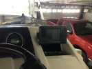
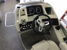
Been bit since I posted. The last time I posted, I was installing a replacement Garmin GPS unit because the factory installed one, after about 8 years or so of flawless service, decided to stop tracking and showing charts, shoreline and more. It's a long story but in short, the Garmin support could do nothing to improve the situation. So, I purchased and installed a newer, more improved model. The new one works outstanding. However, I have a problem. I lost my speedo! It stopped working right after the install of the new GPS. There are, about a dozen wires in the harness for that GPS. But, the instructions say to only use the Red and black for obvious destination connections. Then, because the new GPS came with a new transducer, I installed it and ran the cable up to the new GPS unit.

The old GPS was wired with a red, black and brown that went to a white wire in the boats harness. I wired the new GPS in the same fashion, at least I think I did. I thought I'd hooked up all that was needed. But, apparently somethings amiss. I have no speedo.

Sooooo, what I'm asking for is a wiring diagram for a 2014 Bennington 25RCL with the Yamaha 5.3L 350HP. I'm pretty darn sure this speedo issue is GPS related.
Scott
 
Wow, no one can point me to where a wiring diagram might be for a 2014 Benny 25RCL?
Scott
 
Hey Jack,
I surely thank you for this. Very much appreciated.
Scott
 
No problem, you're welcome
 
You can try this, pretty generic. It’s 2012 but doubtful much changed. See 1st post.

 
You can try this, pretty generic. It’s 2012 but doubtful much changed. See 1st post.

Hey SEMPERFI,
That is darn close to what I need. I really appreciate that. May I ask, is that schematic something you had laying around or, did you request that from Benny? The very specific item or area I need is there but vague. This document is the first one I've seen since the beginning of this search that shows and labels the speedometer as being GPS DRIVEN!!!!!!!!!!! My factory installed Garmin Echomap 50S went south or, I should say that part of its operation went south so I bought a new GPS for the boat. But, in the change over, I lost my speedo! In my learning and research, I found that the speedo is GPS driven so, when I replaced the original GPS with a new one, the wires that come from the new GPS that SHOULD provide a signal to the speedo, are DEAD in the new model. CRAP! So, I'm looking for the specific wires from the speedo to the GPS (original Echomap 50S) to tell me what wires went where.
Scott
 
No, if I remember correctly, it was provided by Bennington for the forum. You might reach out to Bennington direct (info from Jack above) and they may be able to help you with that more specific info.
 
No, if I remember correctly, it was provided by Bennington for the forum. You might reach out to Bennington direct (info from Jack above) and they may be able to help you with that more specific info.
Well,
Again I appreciate your trying to help here. I have reached out to Bennington in multiple ways and at least two people. It seems they're dragging their feet. The western field rep and I had a phone conversation 2 days ago and he said he'd get a tech involved to assist with my speedo non-op dilemma. Haven't heard back. All I'm asking for is a simple wiring diagram of our boat to help me with a problem. My local Bennington dealer/service is booked for weeks. And I'm perfectly capable of handling this issue I'm having with my speedometer. I'd just like the wiring diagram to assist in my analyzing process. I have no idea how many different dash layouts and how many types of gauges Bennington used in 2014 on all their boats. A generic wiring diagram gets me close but, I need the EXACT schematic for my boat and my dash and my gauges, as it was built from or in the factory.
Scott
 
Your speedometer gauge is run from the water pitot on your outboard, or your GPS receiver?

I have the Yamaha gauges and it uses a factory supplied receiver that hangs inside the helm. Easy to see and find. Your setup might be different.
 
Well,
Again I appreciate your trying to help here. I have reached out to Bennington in multiple ways and at least two people. It seems they're dragging their feet. The western field rep and I had a phone conversation 2 days ago and he said he'd get a tech involved to assist with my speedo non-op dilemma. Haven't heard back. All I'm asking for is a simple wiring diagram of our boat to help me with a problem. My local Bennington dealer/service is booked for weeks. And I'm perfectly capable of handling this issue I'm having with my speedometer. I'd just like the wiring diagram to assist in my analyzing process. I have no idea how many different dash layouts and how many types of gauges Bennington used in 2014 on all their boats. A generic wiring diagram gets me close but, I need the EXACT schematic for my boat and my dash and my gauges, as it was built from or in the factory.
Scott
why don't you go to justanswer.com and ask them. I don't think you pay anything unless they can help you. It's worth a shot since your looking for the "exact schematic" for your boat.
 
Your speedometer gauge is run from the water pitot on your outboard, or your GPS receiver?

I have the Yamaha gauges and it uses a factory supplied receiver that hangs inside the helm. Easy to see and find. Your setup might be different.
Hey Potomacbassin',
I appreciate you answering here. The Pitot system on the bigger more advanced systems/boats/engines/dashboards went away a while ago. My speedometer is definitely GPS driven. The speedometer has a tag on the back showing: 6Y80-11. When one looks that number up, it's a Yamaha gauge and confirms it's a GPS driven speedo. There are two specific wires leading from the back of the speedo that are for a "NMEA 0183" compatible device. On the harness from the back of my original Garmin Echomap 50S, there are four wires. Two are for power, one red and one black. The other two are for a "NMEA 0183" compatible devise. With all the electrical diagrams I've found in my searches and what's been presented on here from fellow members, none show the actual linkup between the the Garmin and the Yamaha speedometer. THIS is what I'm searching for.
Scott
 
why don't you go to justanswer.com and ask them. I don't think you pay anything unless they can help you. It's worth a shot since your looking for the "exact schematic" for your boat.
Hey Julianna,
Well, I suppose I could go there. I've never heard of that site so, it would be new to me. The way I figure it, Bennington built the boat. They outfitted it with any and all equipment, including a GPS unit inset in the dash. They installed the Yamaha motor and all the accompanying Yamaha related operational gear, including the speedometer and tachometer. I also figure they're a multi-million dollar a year business in building and supplying boats all over the U.S. and maybe the world. And, like many high tech manufacturers, I'm presupposing they KEEP RECORDS on each boat, including WIRING DIAGRAMS!!!!!!

When a person pays several thousand dollars for a boat, as in a Bennington, I figure Bennington would be very happy the person bought one of their boats and would or should be at least somewhat accommodating when it comes to inquiries pertaining to parts or replacement items or WIRING DIAGRAMS!!!! To me, this is just logical. It's not rocket science. A call is made or an email is sent, requesting a wiring diagram for a particular boat, not generic, not non specific, but A PARTICULAR BOAT and a hull I.D. is supplied with request. I mean, I don't think I'm asking for national security nuclear secrets, just a wiring diagram for my boat. How hard can it be to either get up from a desk, go to a file cabinet, look up the boat in question and open the file and grab the wiring diagram and make a copy or, just put it in a copier and send the address to an email so it can be sent to the customer orrrrrr, just look it up on the computer and find the diagram in question and send a copy via email to the customer???? Sure don't seem hard to me.
Scott
 
Last edited:
Hey Potomacbassin',
I appreciate you answering here. The Pitot system on the bigger more advanced systems/boats/engines/dashboards went away a while ago. My speedometer is definitely GPS driven. The speedometer has a tag on the back showing: 6Y80-11. When one looks that number up, it's a Yamaha gauge and confirms it's a GPS driven speedo. There are two specific wires leading from the back of the speedo that are for a "NMEA 0183" compatible device. On the harness from the back of my original Garmin Echomap 50S, there are four wires. Two are for power, one red and one black. The other two are for a "NMEA 0183" compatible devise. With all the electrical diagrams I've found in my searches and what's been presented on here from fellow members, none show the actual linkup between the the Garmin and the Yamaha speedometer. THIS is what I'm searching for.
Scott


Ah, gotcha makes sense. I also have the 6Y8 speedometer, but the GPS signal is fed via a 3rd party antenna (Veethree Insturments) so can't help you there.

But the 6-pin harness on the back of your 6Y8 has a white and blue wire - that's the GPS input. The other wires are for analog fuel level and power IIRC. If it was getting the signal input from your Echomap 50s NMEA 0183 then either Bennington or the dealer used a harness or spliced that into your 6Y8 blue and white wires. I've read your chartplotter may also need to have a setting changed to output that signal.

Best bet is to go to The Hull Truth and ask there question there, a few members are real sharp electronics guys and can help troubleshoot this for you.

Here's my setup:

IMG_8853.jpeg
IMG_8855.jpeg
IMG_9815.jpeg
 
Last edited:
Folks,
This is a long read, but it's detailed as to why I need(ed) what I needed. Read at your leisure. Take coffee breaks.


Hey Potomacbassin,
You're finally hitting close to home here. Bennington has responded as well as the western rep for Bennington. While both are trying to help, they're still not presenting the actual wiring diagram of our boat. Permit me to provide a tid-bit of information on how another part of my mechanical life works. We have a motorhome. It's a diesel unit and is built on a Freightliner chassis. When you (us) become the owner of such a chassis, and prove to Freightliner that it is in fact registered in our name (via normal vehicle registration for our state), Freightliner then offers a form of a membership to *DTNA* or, Daimler Truck North America which owns Freightliner. Once you're all established and setup with Freightliner, like this and any other forum, you setup a user name and password.

When I log into/on that DTNA network, I am now provided with every single bit of information pertaining to the building of OUR CHASSIS, not a generic chassis, not anyone elses, no other chassis, JUST OURS. That site, will allow me to find every nut and bolt, every suspension part, everything that pertains to the brakes (air brakes) and, it gives me EVERY INCH OF WIRING that was done in multiple schematics. It is sooooooo nice to be able to go into that site at anytime, day or night and locate ANY part and part number of something that needs replacing or at least INFORMATION about it.

Now, I know that Freightliner is jusssssst a bit larger in production than Bennington and can afford to do what it takes to setup a network for not only us RV owners but also the thousands and thousands of Freightliner techs out there in the truck service world to utilize. When I need a part or simply need information on a specific part or area or group of components, I jump on that site and within minutes I have any and all information I need to proceed to either purchase a part or move forward with a repair.

I say all this because to me, while it might take a bit of logistics to set the whole program up, Bennington could do the same thing. When the boat is built, a log of all components, wiring, fuel tanks, parts, gauges, engine and related engine controls and more, all could be put into a single file that would or could be accessed by ONLY the registered owner of that particular boat. I have no idea how hard it would be to setup a program like that or Freightliners. Just dreaming I guess.

Anyway, your setup, is very, very interesting. Yes, I already knew the white and blue wires from the 6-pin connector on the back of that 6Y80-11 Speedometer are to be routed to ANY NMEA 0183 device. Any device meaning a Garmin Echomap 50S or other versions, as well as whatever that little box you have too. I'm supposing that that little box is simply a GPS antenna/sending unit, correct? I guess that's a pretty good idea if the boat is not to be issued a dedicated Garmin Chartplotter/GPS/fish finder like ours was. As long as you have something (in GPS form and NMEA 0183 compliant) that can drive that speedometer, you're in great shape.

My main goal of all this, and the inquiry to acqisition of a wiring diagram that is specific to our boat was to find out the EXACT wiring of those blue and white wires to the output wires on our replacement GPS unit for the boat. You see, our factory installed Garmin Echomap 50s quit tracking and providing of shoreline and mapping after almost 10 years of great service. Garmin stated they could do nothing to help because it was an outdated unit. Great! Now what?

All other functions of that Garmin Echomap 50s functioned just fine. It just didn't know where it was or was going or where it has been. For us boaters, we kind-a like that function so we can track back to a given spot on lake or the river or what and where ever. Soooo, I looked for the closest sized and equal function unit that Garmin now builds to replace that 50s unit. Not knowing that my speedometer is GPS driven, I picked the closest in size to buy. I ended up purchasing the Garmin Echomap UHD2 53CV. This is a 10 year newer unit than the 50s and has a ton of enhanced features and a way better screen. But, it's not the same exact size so, fittment to the hole in the dash where the 50s was, was a bit of a challenge.

I made it work. Now here's the deal. The number of output wires from the harness on that 50s was/is waaaaaaay more than the new UHD2 53cv unit I have now. But, out of around 10 or so wires from that harness, only 4 are used. A red for positive power, a black for ground, and a blue and brown. The 50s blue output wire was wired to the white wire on the back of the 6Y80-11 speedometer. The brown was left alone and not used. The light blue wire with the white wire from the back of the speedo was (and still is) connected to ground.

The new Echomap UHD2 53cv, ONLY has four wires from its harness. A red, a black and a brown and blue. The red and black are obvious. I hooked the blue wire to EXACTLY where the blue wire from the old 50s was hooked to, the white wire from the speedo. I thought, great, that was easy.

We took the boat out and what's this????? NO SPEEDOMETER!!!!!!!!!!! I had no idea where to even start to look to find the issue. All I knew was I'd changed GPS units and wired in the new one EXACTLY like the old one was and now I have no speedometer. When I got Garmin on the phone, we talked for quite a while and I told him that I'd done quite a bit of research as to wiring our boat and the Garmin but was stumped in my predicament. I told him that the factory wiring instructions for the new UHD2 53cv state to disregard the blue and brown wires when wiring up the new unit. But, I'd found other instructions that stated that, those brown and blue wires are to be wired to a NMEA 08183 compliant device.

And that, when I finally found a wiring diagram that was close my Bennington 2550RCL pertaining to the speedo/tach etc. it shows the white and blue wires to be wired into a NMEA 0183 compliant device. Hmmmm. That is when I learned that my speedo is GPS driven. But, I was still not getting any speedo even though the new unit was wired exactly like the old 50s was.

He finally found out why I had my issue. He stated that for some odd reason, Garmin disconnected the brown and blue wires INSIDE the UHD2 units!!!!!!!! He had absolutely no explanation as to why they did that. And THAT'S why I had no speedometer, simply because the output of that blue wire was/is NOT THERE, IT'S A DEAD WIRE!!!!!!!!!

I needed a specific wiring diagram from Bennington to actually see which wires on the Garmin were wired to which wires on the back of the 6Y80-11 Yamaha speedometer. I know the speedo worked with the 50S but did/does not work with the UHD2 53cv which has the same exact colored wires. I have provided myself with a solution to this dilemma. Since all but the chart plotting and tracking functions still work on the 50s, I thought I'd experiment with something. I parallel wired the old 50s unit to the hookups of the new unit. Only, since the brown and blue wires from the new unit are dead, those are out of the equation. I wired the blue wire from the 50s, back to the white wire from the back of the speedometer where it had been hooked up previously. The light blue wire that parallels the white wire from the speedo, is still connected to ground.

I then hooked up the boat to the truck (since all this work was done in the garage) and me and the wife headed out on the street towing the boat. I had turned on all the power and ignition which would energize the speedo. YAHOOOOOOOO! As I was driving the truck, the wife was riding in the boat and using our phones, we communicated the findings of whether or not the speedo was working again. Apparently it took a minute or two to log in and or register with the speedo but that hidden (under the helm) 50s unit was picking up GPS signals and now sending them to the speedometer was we were towing the boat down the street, yaaaaaaaay! I verified what she was reporting as the speed, by telling her my speedo in the truck was the exact same!

So, essentially, since that experiment was a success, I now have TWO GPS units in the boat. One is the new one mounted very close to where the old one was. And the second one is going to be mounted securely under the helm, with its only function to be to supply the speedometer a signal. That's my story and I'm sticking to it! Sorry for the War and Pease novel but, these are the details of why and where I've been the last few days and why I was so persistent in trying to obtain wiring from Bennington that is specific to our boat. Not all Benny's get a GPS so, generic wiring was not going to work.
Scott
 
Garmin probably disconnected the other two wires as the unit doesn't support transmitting data, just receives data from the transducer. It looks like that model is one of their cheaper chartplotters so having limited options and hardware is part and parcel to the lower cost. Compare it to what a GPSMap unit can do and there's a reason those units are many, many thousands of $$$. But of course unnecessary for most pontooners.

If you're the frugal type like me that's a great way to solve your issue! But if down the road you want to replace the old unit for one of those Vee Three GPS transmitters they run $150-200.

Lastly I don't think you're going to have much of a receptive audience airing your frustrations about the wiring diagram - besides toeing the TOS line I just don't think it exists especially as it relates to the wiring of ancillary devices like a Garmin. There is so much customization possible in these boats the designers likely aren't making wiring CAD for every build. Some installer just bolts it on, tests it and out the factory it goes.
 
Hey Poto,
Thanks again for your answer. Since the 50s unit was installed at the factory, at least I think it was since there's a blow-molded recess in the dash that's a perfect recess for it, I have no idea what the cost of it was when it was new. Was it or could it have been cheaper than the Echomap UHD2 53cv that I replaced it with, not a clue. Now, the 50s did/does have about 6-8 more wires in it's harness than the UHD unit does. And that's for two ports of transmit and receive, alarm, acc and one or two other items. So, maybe the 50s was quite a bit more expensive.

As for airing my frustrations over the wiring diagram, well, none of any of my frustration was directed at anyone here on this forum, unless you count Bennington employees if they're watching. My issue was that part of my boat ceased to function. And through some of my own research and some help from folks on here, I found that my problem was electrical and that like anything that's electrical in either the automotive world or the boating world, ya gotta start somewhere in diagnosing the problem and that quite often is assisted with the use of a wiring diagram or schematic. General schematics were of SOME help but, they don't answer the specific problem I was/am having. Not being an electrical engineer or wizard, I was hoping they had what I needed to help me through this. I have watched the video of Bennington building their boats. It's impressive for sure. This issue was the first time I've had a need to ask for assistance in a matter on this boat since we purchased it about 3.5 or so years ago.

If Bennington does not have a specific wiring diagram or schematic of our boat, as it left the factory, then fine, all they have to do is TELL ME THAT. For now, my issue is resolved due to the parallel wiring of the 50s unit AND the UHD2 unit. Not being a GPS wizard, I had no idea that little box of yours existed. I zoomed in on one of the photos you linked and found the part number. I found a new one on ebay for $75.00 without the original packaging. But, even if I had knowledge of that little box and its capabilities of transmitting data to my speedometer which would have been and answer to my issue, I'd have still had the problem of no tracking or chart plotting, shore line, or any idea where we are/were/gonna be if I'd have left that 50s installed in the dash.

May I ask, What is "TOS" line? And also, the way I figure it, Bennington was not going to send a boat out without a working speedo. So, in this particular boat, and who knows how many others had the same Garmin unit installed, they installed the Garmin Echomap 50s which along with other functions, is also a GPS receiver and was/is capable of transmitting data through the white and blue wire to the back of the Yamaha 6Y80-11 speedo. And if they did more than one boat like this, I would have thought that GPS install and its applicable wiring, would have been on a diagram someplace. As of yet, it's not apparently so.

So, this has all be a learning experience by far. By the way, in talking with a Garmin customer service tech, he did inform me that the next unit up from mine (the UHD2 53cv) that DOES have transmitting capability of data on the NMEA 0183 or even the NMEA 2000 is the Garmin Echomap UHD 73SV. That's a 7" model and would in no way fit in the area provided in my dash. So, at present, what I did in purchasing the 53cv, as you can see in the pics, was pretty much my only option. One pic shows the original 50s inset in the dash. And the other shows the UHD2 53cv in its cradle. The cradle was the more logical choice in this matter, based on available space.
Scott
Scott
 

Attachments

  • 71277240036__3BFB3E20-77F5-4488-9F6A-E4B6D5F4550B.JPG
    71277240036__3BFB3E20-77F5-4488-9F6A-E4B6D5F4550B.JPG
    82.7 KB · Views: 4
  • IMG_1394.JPG
    IMG_1394.JPG
    150.1 KB · Views: 4
Last edited:
No I get it - everything you did makes perfect sense. I think sometimes we expect manufacturers to come through on the technical advice side especially given the purchase price. In my humble opinion even though ultimately you didn't get what you desired Bennington and Garmin are two of the more helpful OEMs out there. Others brands completely ghost you after sale and getting anyone to even pick up the phone is like trying to get a slimy tennis ball out of a Labrador's mouth. Just not a pleasant experience.

It can be like walking the desert sometimes but a bunch of the members including myself will try as best we can to help!
 
Status
Not open for further replies.
Back
Top