Jim_R
Well-Known Member
- Messages
- 442
- Reaction score
- 37
I didn't want to clog up the Perimeter Lighting thread, so created this related topic. This will start out as a DYI on cutting and wiring smaller individual lights from an LED strip, then (once it stops snowing and acting more like spring outside here) cover install of the individual light strips into storage areas on my 2275 RL. While I am using waterproof 3528 single color LED strips, the cutting and wiring concepts extend to RGB strips using different components as well.
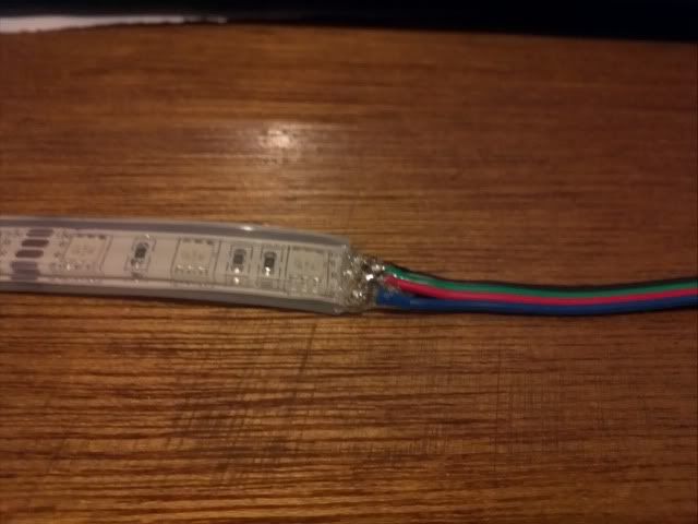
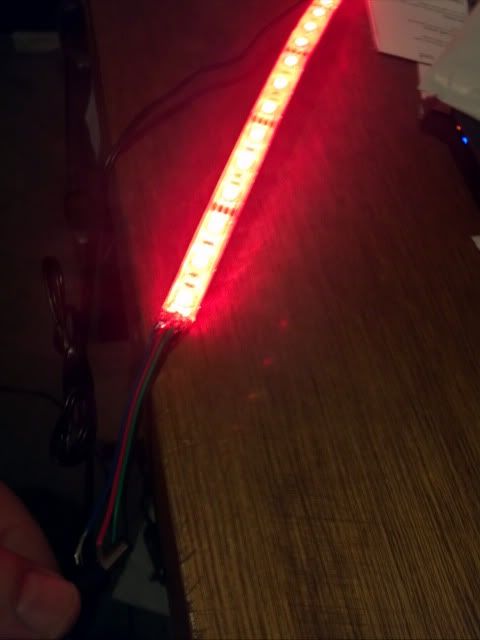
Here's a pic comparing an RGB strip using 5050 single chip components (top), and a single color 3528 strip (bottom).
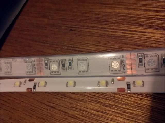
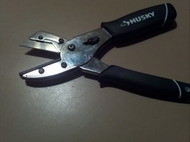
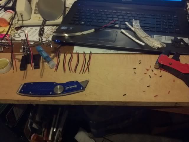
The 5050 RGB strip has a cut line drawn though the copper contacts, the 3528 strip, not so much, but the contacts are visable enough. Each strip has a cut area every two inches allowing for smaller strip segments to be created. When cutting the 3528 strip, I found it easiest to cut at the farthest most right edge of the copper contacts, making sure to leave some space before the black resistor. BTW - the black resistor is on the negative trace, knowing this helps keep +/- connections straight. The waterproof strips pictured are coated with silicone, but can be cut fairly easily with a razor knife. The tool below, which I found at Home Depot cuts them like butter.
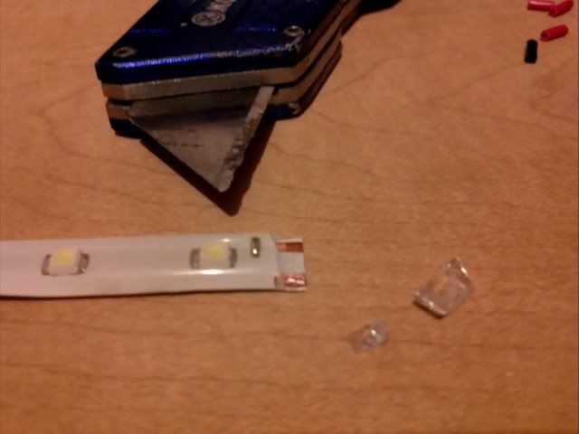
Once the strip section is cut to the desired length, with waterproof strips, the silicone covering must removed from the copper contacts.
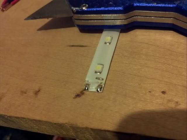
Next, we want to add a blob of solder to each copper contact. I used a relatively low power soldering iron (25W) and rosin core solder. (I am by no means a soldering guru - this is pretty easy stuff.)
Next tin the stranded wires you wish to use. I stayed with red +/ black - conventions, and created 3" leads.
Next apply solder to the wire leads tinning them.

See? Told ya I was no soldering guru. Next, using my conventions heat the tinned end of the black wire lead with the soldering iron for about 3 seconds, place against the glob of solder on the strips copper contact and apply additional heat if necessary to solder the lead to the pad. Repeat for the red/+ side.

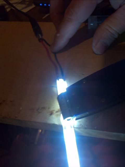
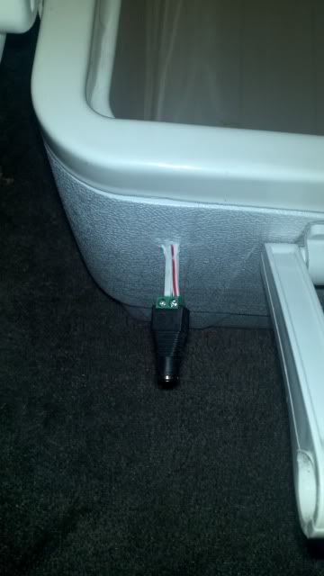
My next steps are to test the connectivity of the new connections, I used a 12V laptop power supply where the inside of the barrrel connector was positive and the outside negative.
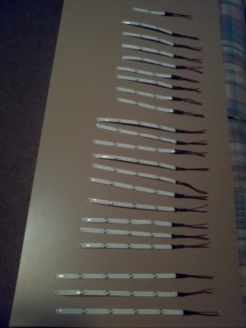
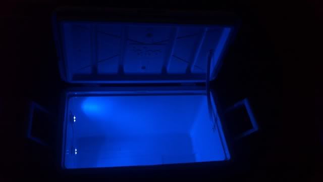
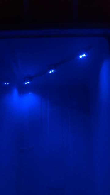
With connectivity verified, I go on to shrinkwrap, retest, then seal the cut end and wire ends with seal-all. Probably overkill. For me the end result was this:\
More to come with spring thaw...
Here's a pic comparing an RGB strip using 5050 single chip components (top), and a single color 3528 strip (bottom).
The 5050 RGB strip has a cut line drawn though the copper contacts, the 3528 strip, not so much, but the contacts are visable enough. Each strip has a cut area every two inches allowing for smaller strip segments to be created. When cutting the 3528 strip, I found it easiest to cut at the farthest most right edge of the copper contacts, making sure to leave some space before the black resistor. BTW - the black resistor is on the negative trace, knowing this helps keep +/- connections straight. The waterproof strips pictured are coated with silicone, but can be cut fairly easily with a razor knife. The tool below, which I found at Home Depot cuts them like butter.
Once the strip section is cut to the desired length, with waterproof strips, the silicone covering must removed from the copper contacts.
Next, we want to add a blob of solder to each copper contact. I used a relatively low power soldering iron (25W) and rosin core solder. (I am by no means a soldering guru - this is pretty easy stuff.)
Next tin the stranded wires you wish to use. I stayed with red +/ black - conventions, and created 3" leads.
Next apply solder to the wire leads tinning them.
See? Told ya I was no soldering guru. Next, using my conventions heat the tinned end of the black wire lead with the soldering iron for about 3 seconds, place against the glob of solder on the strips copper contact and apply additional heat if necessary to solder the lead to the pad. Repeat for the red/+ side.
My next steps are to test the connectivity of the new connections, I used a 12V laptop power supply where the inside of the barrrel connector was positive and the outside negative.
With connectivity verified, I go on to shrinkwrap, retest, then seal the cut end and wire ends with seal-all. Probably overkill. For me the end result was this:\
More to come with spring thaw...
Last edited by a moderator:


")