I wanted to circle back and provide an update to this post, i did move forward with this project last summer with great success and wanted to post the process of what i did for anyone else who maybe trying to do the same thing. This was done on a 2013 22 SLX with a single battery.
Under Seat LED and Storage compartment LED Lighting Project with additional rocker switch cluster:
Since we started doing a lot of night boating, it quickly became apparent that the single courtesy light installed in the helm was not sufficient.
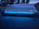
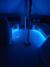
There were 2 issues we wanted to solve, provide indirect lighting to the deck to be able to walk around at night safely, and add lighting under the helm and in the changing room to be able to access storage at night and in the event of mechanical issues, be able to see the battery, oil tank, and under the helm wiring at night.
We thought about adding lighting inside the seat compartments but opted against it as we hardly use them for any meaningful storage.
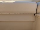
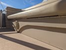
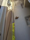
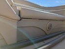
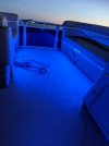
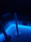
We added RGB LED Light strips under both bow seats and under the rear L bench. We then added White Only LED light strips under the helm and in the rear changing station.
The RGB LED light strips for under the seats were all cut from a single 32’ LED Strip and attached to the seat base directly under the seat cushion using the LEDs double sided tape which came pre-attached, i was worried at first about how this would hold up to heat, water, and cold and so far no issue at all. The wire is then run under the seat into the seat base and is sent through the existing in deck hole installed by the manufacture to power the sound system speakers. Each RGB LED strip was wired with 22 awg tinned 4 cable extension cable soldered onto the LED light strip and covered with 3-5” of shrink wrap.
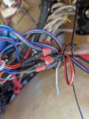
In order to get this cable through the speaker wire hole I had to remove the factory installed silicone, which was replaced after the install. The benefit is this project did not require any new holes to be drilled through the seat or the deck. The LED Cables were then routed under the deck along the support frames held in place against the existing speaker wires with zip ties inside a protective wire conduit tubing.
The cables all were routed back to the helm and came up through the existing hole where the manufacture ran all the wiring into the helm, again no new holes needed to be drilled through the deck.
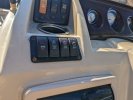
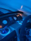
I used the Auxiliary cable under the helm, supplied by the factory labeled “For Customer Use” on the wiring schematic, to power an additional rocker switch set I purchased and installed in the helm which added 4 new rocker switches to the helm. The under-seat LED and the storage LED are each powered by their own dedicated switch from this new rocker switch cluster. This allows the under-seat and storage lights to be turned on and off independently and reduces battery drain as the storage lights are not always needed. We also wanted to have a switch for a saltwater washdown as well as a spare switch for future modifications. So, this project used 3 of the 4 rockers on the new switch set.
While I could have used the Aux switch or Livewell switch pre-installed by the manufacture, these switches were already used by the GPS/Fish finder and the VHF Radio. So, a new rocker cluster was needed. (If you could not tell I like all my electrical components on their own switches.
The switch came pre-wired and includes an illumination locator light as well as a power on indicator light. The locator light is constant on directly feed by the battery while the power indicator only illuminates when the switch is on. Since I did not want the constant power draw of the locator light. I modified the rocker switch wiring, so the switch is only illuminated when the engine is running.
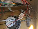
Each LED Strip were run in parallel, so each LED Strip had its own cables running back to the helm. There were 3 cables for the RGB light strips for under the seat which were connected to the RGB Controller box that came with the LED light set. The white LED for the storage compartments had 2 cables. So, each light strip is getting direct power.
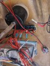
The LED added to the changing room was wired by running the power cable down the existing hole used for the battery wires and was routed along the frame following the existing cables heading to the helm. Again, these cables were in protective conduit and zip tied to the existing cables. Accessing these cables did require the removal of a protective sheet of aluminum under the deck, which unfortunately was riveted into place and had to be drilled out. this was reinstalled after the modification, again by riveting it in place.
All wire connections were solder together and covered with 3-5” of shrink wrap for waterproofing.
I can try to get pictures if anyone is interested, and I am willing to provide more details to anyone who maybe trying this themselves.
For this project I used the following Materials, all from Amazon. While there are more expensive, possibly better suited, options available these materials have lasted well so far and show no signs of any issues as of yet.
RGB Light Strip 32.9 feet (under seat lights)
https://www.amazon.com/gp/product/B07JN28KP3/ref=ppx_yo_dt_b_search_asin_title?ie=UTF8&th=1
22 AWG 4 wire RGB Tinned Extension Cable
https://www.amazon.com/gp/product/B08JTZCJV1/ref=ppx_yo_dt_b_search_asin_title?ie=UTF8&psc=1
White LED Strip 16.4 feet (storage compartment)
https://www.amazon.com/gp/product/B00UI1DVP2/ref=ppx_yo_dt_b_search_asin_title?ie=UTF8&th=1
22 AWG tinned extension cable
https://www.amazon.com/gp/product/B08DNH2HS3/ref=ppx_yo_dt_b_search_asin_title?ie=UTF8&th=1
Rocker switch
https://www.amazon.com/gp/product/B08R1VB3LL/ref=ppx_yo_dt_b_search_asin_title?ie=UTF8&psc=1
Wire Conduit – black – ¼” 100’
https://www.amazon.com/Alex-Tech-25ft-Tubing-Conduit/dp/B07TDGMDW4/ref=sr_1_1?crid=37CKUWBBFC2C4&keywords=Alex+Tech+25ft+–+1/4+inch+Split+Wire+Loom+Tubing+Wire+Conduit+–+Black&qid=1641921770&sprefix=alex+tech+25ft+1/4+inch+split+wire+loom+tubing+wire+conduit+black,aps,101&sr=8-1